All the browser items may have a description, a stereotype (sometime without special meaning for BOUML, the default stereotypes may be defined for some types of item, and there are modeled stereotypes defined in profiles and simple stereotypes beign only a text), and user properties. The browser item's stereotype may be showed/hidden through the Miscellaneous menu.
The bold font is used when an item is modifiable, an item is read-only when you do not have the write permission for the file(s) supporting it (see Project files). The system items supporting of the plug-out's API (for instance UmlBaseClass) are also read-only, this help you to not modify them to have a chance to remain compatible with the future versions.
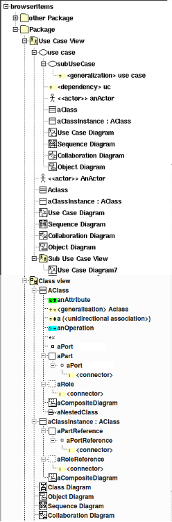
In Bouml there are 4 special types of containers, call views. Views can exist at many levels. These are used to provide structure and organization for diagrams and model elements. The sample browser items figure at the top of this page show the kinds of diagrams and model elements that can be put in each type of view. The context sensitive menus lets the user create only those diagrams and model elements appropriate to the particular type of view.
When you create a new item, this last is placed at the end of the items of the same container, using the left button of the mouse as for a drag&drop it is possible to move an item to place it in an other container (except for the relations) or to change the items order. The drag & drop from the browser to an opened diagram is also possible when it is legal. When you drag an item it1 on a non-container item it2, it1 will be placed just after it2 at the same level. When you drag an item it1 on a container item it2 which may contain it1, it1 will be the first it2's children, in case it1 may be moved in it2 or after it2, Bouml ask you to choose.
Multiple selection is not allowed in the browser using the classical way, I consider that it is to simple to loose a multiple selection through a wrong mouse click. I replace classical multiple selection with the possibility to mark browser items through the menu appearing on a right mouse click, or through a control left mouse click. Marked items are written on a red background, and may be moved or duplicated (under condition) :
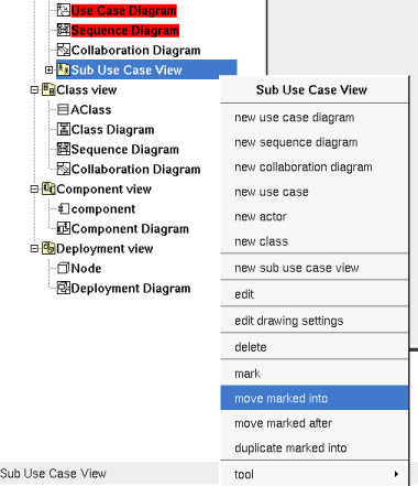
On the example above at the menu appearing on the use case view propose to mark it, to move the marked items into it, to move the marked items after it (in this case only the order of the items is modified) or to duplicate the marked items into it. The menu is context dependent, for a marked item it proposes to unmark the item, or to unmark all the marked items, and for instance for a component view it just proposes to mark it because the two marked diagrams cannot be placed into the component view or after (the marked diagrams cannot be placed into the package containing the component view).
When you remove an item from the model,
the icon contains a red cross (for instance
![]() ),
note that a deleted item is never saved when you save your
project, but it may be undeleted with or without its children until
you close the project. Sometimes it is not possible to delete an
items because this one contains read-only items or is referenced by a
read-only relation.
),
note that a deleted item is never saved when you save your
project, but it may be undeleted with or without its children until
you close the project. Sometimes it is not possible to delete an
items because this one contains read-only items or is referenced by a
read-only relation.
The icons in the browser can be changed by using stereotypes defined in profiles, in some case these icons can also be used in the diagrams.
A double mouse click on an item allows to edit it except when the item have an associated diagram, in this case the diagram is showed. The other mouse buttons show a menu depending on the item kind.
control s is a shortcut to save the project
control shift s is a shortcut to save the project in a new one
control os is a shortcut to open a project
control d and suppr are a shortcut to delete the selected item
A Package (may be the project itself) is first something like a directory and may contain :
packages
relations
A package may indicate where the code must be produced by the generator for each language, and may specify the C++ and Php namespace / Java package / Idl module. A generator producing code for an artifact looks at the package containing the deployment view where is the artifact to get these information.
A package stereotyped profile is used to define a profile.
Refer to package and profile for more information.
A use case view may contain :
sub use case view
classes, an actor is just a class having the stereotype actor
Refer to use case view for more information.
A class view is used to design the classes and may contain :
Refer to class view for more information.
A component view may contains :
Refer to component view for more information.
A deployment view may contains :
Refer to deployment view for more information.
A use case is ... a use case, but also a browser container and may contain :
use cases
classes
relations
Refer to use case for more information.
A class is the support to define a class (!), an interface, an enum, an union, a struct, an exception, or a valuetype, or a table, depending on the language. The stereotype specify what a class is, the way a stereotype is translated for each language may be specified through the generation settings
A class stereotyped stereotype define a stereotype in a profile.
A class may contain :
(nested) classes
relations / foreign key
attributes / columns / keys
The order of the class's sub-items is very important because it is followed by the C++/Java/Idl generators.
Refer to class and profile for more information.
They are two kinds of relation : the relations between classes whose are considered by the source code generators, and the relations between the other items (inheritance and dependency)
To add a relation you have to use a diagram (obviously the relation drawing may be deleted just after !), it is not possible to add a relation through the browser. It is also not possible to move a relation out of the items containing it.
The icon in the browser indicate if a relation between classes is public (+), protected (#) or private (-). The protected visibility is translated in private in Idl.
A bi-directional relation between classes is supported by two items in the browser.
Generally the stereotype of a relation between classes is used to specify how a relation with a multiplicity different than 1 is translated in each language (refer to default stereotype and generation settings), for instance to produce a vector. The friend stereotype is a special case for a dependency and is used to produce a C++ friend declaration. Between classes stereotyped table representing MySQL tables a relation support a foreign key.
Refer to relation for more information.
There is not restriction for the attributes, an attribute's type may be a class or an int for instance. In a MySQL table an attribute support a column or a (non foreign) key
The icon in the browser indicate if the attribute is public (+), protected (#) or private (-). The protected visibility is translated in private in Idl.
Refer to attribute for more information.
The icon in the browser indicate if the operation is public (+), protected (#) or private (-). The protected visibility is translated in private in Idl.
Refer to operation for more information.
 Port
PortUnder a class there are true ports, under a role/part or a role/part instance there are reference to a port defined under a class.
A reference to a port may contain :
Refer to port for more information.
 Part
Part
 Role
RoleUnder a class there are true part/role, under a instance of a class they are role/part instance.
Part/role and part/role instances may contain :
Refer to part/role for more information.
An extra member is an alien allowing you to specify directly the generated code for each language. This allows to manage non UML items, for instance C++ pre-processor directives, Java attribute initializations etc ...
Refer to extra member for more information.
A modeled class instance, a sequence diagram , object diagram or collaboration diagram may contain modeled class instances and graphical classes instances (out of the model).
A class instance may contain :
Refer to class instance for more information.
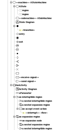
A state represents a state machine, a sub machine, a composite state or a simple state
A state may contains :
sub-states
regions
pseudo states
transitions
receive signals (an action with the stereotype receive-signal)
send signals (an action with the stereotype send-signal)
Refer to state and for more information.
A pseudo state may be :
![]() final state (for reasons of simplification)
final state (for reasons of simplification)
![]() initial
initial
![]() deep history
deep history
![]() shallow history
shallow history
![]() join
join
![]() fork
fork
![]() junction
junction
![]() choice
choice
![]() entry point
entry point
![]() exit point
exit point
![]() terminate
terminate
A pseudo state may contains :
transitions
Refer to pseudo state for more information.
An activity may contains:
![]() parameters
parameters
activity nodes
expansion and interruptible activity regions
Refer to activity for more information.
An expansion region may contains :
expansion and interruptible activity sub regions
![]() expansion nodes
expansion nodes
Refer to region for more information
An interruptible activity region may contains :
expansion and interruptible activity sub regions
Refer to region for more information
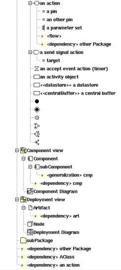
An activity node may be :
![]() activity action (opaque,
activity action (opaque,
![]() accept event,
accept event,
![]() accept timer event, read variable value, clear variable value, write
variable value, add variable value, remove variable value, call
behavior, call operation, send object,
accept timer event, read variable value, clear variable value, write
variable value, add variable value, remove variable value, call
behavior, call operation, send object,
![]() send signal, broadcast signal, unmarshall or value specification)
send signal, broadcast signal, unmarshall or value specification)
control
nodes (![]() initial,
initial,
![]() final,
final,
![]() flow final,
flow final,
![]() merge,
merge,
![]() decision,
decision,
![]() fork,
fork,
![]() join)
join)
Activity nodes may contain :
![]() pins (action only)
pins (action only)
Refer to activity action, object node and control node for more information.
A component is an autonomous unit with well defined interfaces that is replaceable within its environment.
A component may contains :
relations
components
Refer to component for more information.
Artifacts are basically used to produce source file(s) when the stereotype is source, or to specified how libraries or an executable are composed.
A source artifact is (potentially) associated to classes, but you may directly give its source(s) contain for instance to define the C++ main function. A database artifact is (potentially) associated to classes stereotyped table. The other artifacts may be associated to artifacts.
Note : In the very old release of BOUML (up to the 1.5.1), the behavior of the artifact was defined at the component level.
An artifact may contains :
relations
Refer to artifact for more information.
To specify how the deployment is made, a node may represent a CPU, a device etc ...
Refer to node for more information.
Refer to use case diagram for more information.
Refer to sequence diagram for more information.
Refer to collaboration diagram for more information.
Refer to class diagram for more information.
 Class Composite diagram
Refer to class composite diagram for more information.
Refer to activity diagram for more information
Refer to state diagram for more information
Refer to object diagram for more information
Object Composite diagramRefer to object composite diagram for more information.
Refer to component diagram for more information.
Refer to deployment diagram for more information.
![]()
Previous : top level menus
Next : package