
This tutorial is written to help you to use BOUML for the first time, only few features of BOUML are exposed here, but a full description of BOUML is given in the reference manual.
The tutorial must be read in order because I will not repeat each time the general commands to call a menu etc ...
Starting
When you execute BOUML the following message appears, hit ok this time, but you will have to define you own identifier for an effective usage of BOUML :
The BOUML window appears (the drawing is dependent on the used release of Qt, here the 2.4 under Linux to be compatible with the Windows release) :
![]()
The bouml window is composed of three parts :
The left sub-window display a browser presenting your project, the navigation may be done by the mouse or the keyboard's arrows. The bold font is used when an item is modifiable, an item is read-only when you do not have the write permission for the file(s) supporting it.
The bottom-right sub-window is used to display/modify the comment associated to the current selected item.
The top-right part is used to display/modify the diagrams, these ones may be maximized or minimized.
Obviously the respective sizes of the sub-windows may be changed, placing the mouse on the separation between them. Note : if you have at least a dual monitor configuration the better is to set the environment variable BOUML_LIMIT_DESKTOP, see here.
At this level you have to create a new project, or to load an already existing project.
Create a new project
Here we create a new project : in the menu Project choose new, a file dialog appears (its aspect depend on the used system and window manager) and you have to select the directory where the project will be placed and its name, I choose the project foo placed under /tmp :


In this case BOUML creates the directory foo under /tmp, and places some files in /tmp/foo including foo.prj which is the file to load when you will re-load this project. Note : do not rename or delete the files produced by BOUML nor the directory itself !
A new dialog appears :

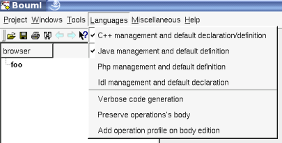
Following the recommendation, I set for instance the toggle for C++ and Java in the Language menu (we will see why later) :
The name of the project appears in the browser, the project is the top level package, a right mouse click on it produces the menu :

As you can see, a package may contain other packages and some views : use case view, class view, component view and deployment view.
View, Use case
Bouml uses views in a project to organize and structure the model elements and diagrams. The different types of views provide different context menus listing the diagrams and model elements that can be created in it.
To define use cases we need to have a use case view, so we choose new use case view :

Bouml asks for the name of the view, to change it later the use case view must be edited through a double mouse click, or choosing edit in the menu appearing on a right mouse click, showing the use case editor :

Diagram
To create a use case diagram in this view, do a right click on the use case view and choose new use case diagram :

The name is also asked, to change it the use case diagram must be edited choosing edit in the menu appearing on a right mouse click. Contrary to the non diagram items, a double click on a diagram show it :

Add elements in a diagram
To create and place a use case in the use case diagram you have two ways :
to do a right click on the use case view and to choose new use case, then to drag it from the browser to the diagram,
or to hit the ellipsis button in the top of the diagram sub-windows, then to hit somewhere in the diagram sub-window. Note that the use case is created in the view containing the diagram, this will be the same thing in the others case whatever the diagram except for the states machine.
Let's Withdraw the name of the use case.
To move the use case in the diagram, do a left click on it and move the mouse click down, the name follow the use case but the name may be moved independently, for instance to place it in the middle of the ellipsis. You may also select the use case and to use the arrows of the keyboard.
Create an actor named Customer like you create the use case, to have :

Note that an actor is in fact a class, when the stereotype is actor the icon shown in the browser is an actor, else a class. To change the stereotype edit the class (double mouse click on the class, or choosing edit in the menu appearing on a right mouse click on the class), choose among the predefined list of stereotypes or enter a new one, read the reference manual to change the predefined list of stereotypes.
The use case picture may be resized moving the points appearing when you click on the use case. The actor can't be resized.
You have to ways to draw the association : a simple line as UML recommendation, or an arrow. Hit on the desired icon, left click on the actor, move the mouse click down up to the use case and release the click :

The lines may be broken during the initial construction if you release the click out of any item, or after the construction with a left mouse click on the line and moving the mouse click down. To remove a point in a line, double left click on it, or right click to show the menu and choose remove from view. To abort a line during its construction : double click.
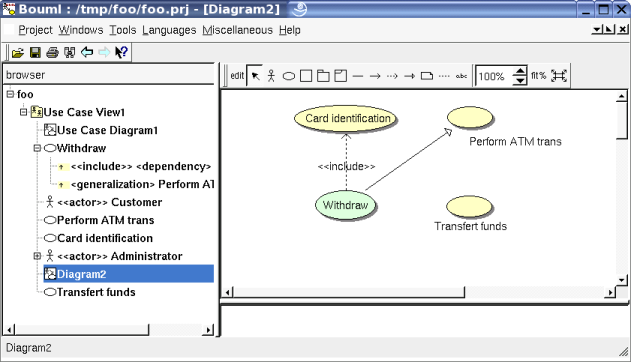
Add new elements in the diagram like this (edit the dependency to set the stereotype include) :

As you can see, the generalizations and dependencies are visible on the browser, their menu (on a right click) in the browser allows to navigate to the target.
If you edit the generalization from Withdraw you will have a simple dialog, this is not the case for the generalization between the actors because this inheritance may produce source code : an actor is a class.
Remove an element in a diagram
To remove something in the diagram, select the desired elements (left click on it) and press Suppr or call the menu and choose remove from view. Note that this is not possible to remove a label.
Delete / undelete browser element
To delete something from the model, use control-d or choose delete from model, you may also do that on the item in the browser. For instance if I delete the Administrator :
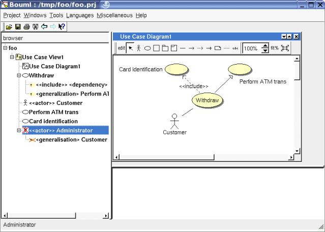
Obviously the Administrator and the generalization disappear from the diagram, but this is not the case in the browser : they are just marked deleted. Their menu is modified : you may undelete just the Administrator or this one and all his children (undelete recursively), you have no menu for the generalization because it can't be undeleted while Administrator is deleted !
Note that the deleted elements are not saved, if you reload the project the deleted elements will be definitively lost.
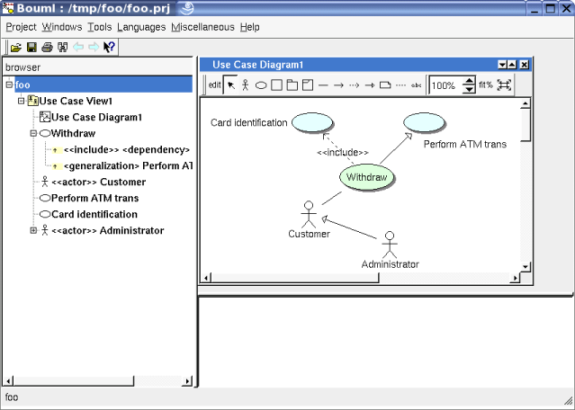
Undelete the actor and the generalization, they do not reappears in the diagram.
Reinsert the actor in the diagram, using a drag&drop from the browser to the diagram sub-window, or hit the actor icon in the diagram then click somewhere in the diagram and select Administrator in the proposed list. The generalization is not automatically drawn, but this may be the case for a class diagram (depending on the drawing settings). To draw the generalization do a drag&drop from it the browser to the diagram.
Drawing settings
The colors and other drawing characteristics may be changed setting the drawing settings. If you prefer to always have blue use case the better is to call the menu on the project (i.e. on foo in the browser) and choose edit drawing settings, go in the last tab and change the default use case color. If you do that on a sub level, for instance on the diagram, the scope of the new value will be limited on the chosen level and recursively on all its children. The value specified on a upper level is followed while the setting values default, this is the case by default except at the project level (there is nothing upper).
So, we change the color of the use cases to blue at the project level, now all are blue. We call the menu on Withdraw (in the browser or the diagram, doing a right click) and choose edit drawing settings, change the color which is default (to follow the rule defined upper) to green :
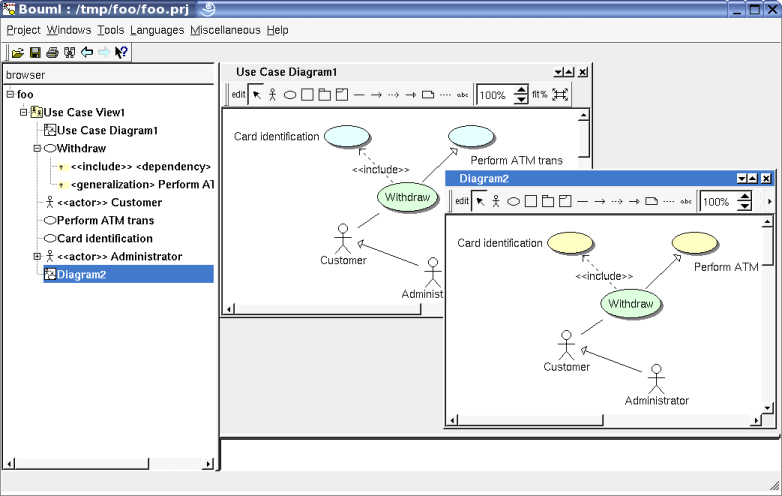
Now, in the browser call the menu on the diagram and choose duplicate, this duplicate the diagram and call the dialog on the clone to change the name for instance. Hit ok and open the diagram, yes this is a clone, edit its drawing setting to have yellow use case and of course :
Select elements in a diagram
To select several elements in the diagram, for instance to move them :
control-a select all
a left mouse click with the control key down allows to add/remove the pointed element from the selection list
doing a left mouse click down out of any item and moving the mouse click down define a rectangle, on the mouse clock on all the included items will be selected
choosing select linked items in the menu of an object in a diagram allows to select all the items having any line between them, practical isn't it (all the elements here) ?
z-dimension
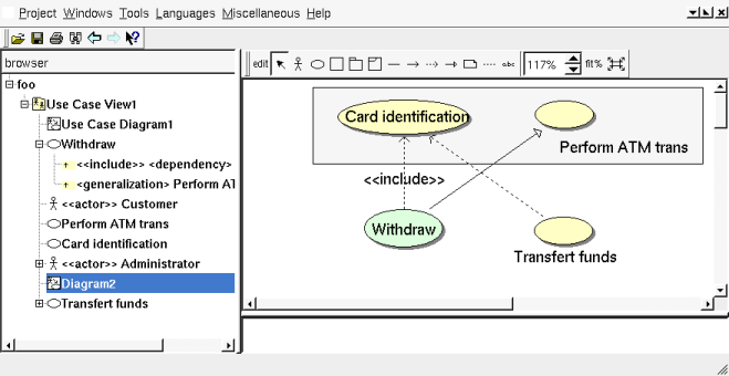
Add and remove elements in Diagram2 to have (the diagram was maximized) :
Add a subject and resize it to have :

Now try to add a dependency from Transfer funds to Card identification : you can't. What is append ?
Because you add the subject after Card identification, the subject is upper the use case and BOUML considers you try to do a dependency from Transfer funds to the subject.
If you change the color of the subject this is more visible :

Don't panic, contrarily to other UML tools you don't have to redo all, just call the menu of the subject and choose lower, and now you may add the dependency.

Zoom, window size, diagram format
When you open a diagram the scale is set to 100% and the window size is unfixed.
When you change scale using the little arrows or directly writing the desired value inside the spin box (practical to come back exactly to 100%) the size of the arrows is unchanged, this allows to see them even with a small scale, and to not use a large area for that when the scale is hight.

The dashed lines show the limits of the diagram (canvas size), you can see something placed outside these lines. By default the format of a diagram is European ISO A4. To Change the format of a diagram, call its menu from the diagram sub-window and choose the format (the menu of the diagram in the browser doesn't allow to do that). The format 'A' corresponds to the USA letter, 'B' to USA large and 'C' is even larger. To set the format used for the diagram you will create in the future, choose the sub menu Diagram default format of the menu Miscellaneous.
fit% change the scale to be the larger one allowing to see all the diagram elements depending on the diagram sub-window size. This may also be done choosing optimal scale in the diagram menu.
In the opposite you can automatically change the size of the
diagram sub-window to see all the diagram elements for the current
scale choosing optimal window size in the same menu or through
the button
![]() .
.

Closing then re-opening the diagram the window size and the scale are reset by default. To save the current window size and scale to restore them the next time you re-open the diagram, choose set preferred size and scale in the menu of the diagram in the diagram sub-window (not possible from the menu in the browser).
Export diagram picture
There are several way to export a diagram picture :
to print it : if needed open the diagram to show it, use the button which icon is a printer on the top left of the BOUML window
to copy it, for a paste in an other program : if needed open the diagram to show it, choose the entry copy visible picture part in the diagram menu (not possible from the menu in the browser). The visible part is the part of the diagram which appears depending on the diagram sub-window's scrollbars position. To copy all the elements even the non visible ones, choose copy optimal picture part.
to save the picture in a PNG file : if needed open the diagram to show it, choose the entry save visible picture part (png) in the diagram menu (not possible from the menu in the browser). To get all the elements even the non visible ones because of the current size of the sub windows, choose the entry save optimal picture part (png)
to save the picture in a SVG file : if needed open the diagram to show it, choose the entry save visible picture part (svg) in the diagram menu (not possible from the menu in the browser). To get all the elements even the non visible ones because of the current size of the sub windows, choose the entry save optimal picture part (cvg).
to use a plug-out, for instance the HTML generator. In case an exported diagram is not already opened, the scale and the size of the saved part are the default ones except if you had specify them using set preferred size and scale.
Sub package, class view, class diagram, class
Now we want to design classes to generate code.
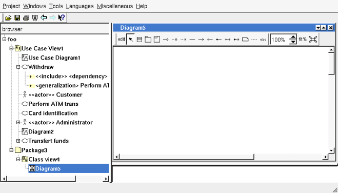
For that we have first to create a class view, and why not we don't want to place it directly in the project package. First call the project menu (right mouse click on the project's name in the browser) and choose new package, name it Package3. Call the Package3 menu and choose new class view named Class view4 :

A class diagram is not mandatory to define classes (except to add relations), but create a class diagram through the class view menu, then open this diagram :

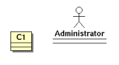
Click on the button which icon is a class and click somewhere in the diagram (it is also possible to create the class using the class view menu in the browser), name the class C1


Because the actors are classes, they can be added in the class diagram, using a drag & drop from the browser to the diagram sub-window, or using the diagram class icon and choosing for instance Administrator hitting 'a' in the combo box or using its arrow. The actor is drawn as an actor, this a default for the classes having the stereotype actor (this depend on the drawing settings of the class, the other special cases are for the stereotypes control, boundary and entity) :
However in the normal case the goal of an actor is not to be used to generate code, and in the generation settings the stereotype actor at class level is translated to ignored in the target languages. To continue without this limitation, edit the generation settings, go in the tab stereotype and replace ignored by class in C++ and other language in the line for actor :

Add attribute and operation
We want to define an attribute named att, and an operation named oper. Call the class menu doing a left mouse click on the class in the diagram or in the browser, choose add attribute then add operation. When you add the members through the diagram their editor are automatically called, not through the browser. The class members are visible in the browser and the class picture :

Because of the default visibility set through the class settings the attribute is protected and the class is public. The class settings may be set at the class view or package levels, following the same principles of the drawing settings.

Edit attribute
One decide that att must be an int, we have to edit it, this may be done through several ways : double click on it in the browser, to call its menu on the browser and choose edit, ot to call the menu of its class in the diagram choosing edit attribute then att. You obtain the dialog :
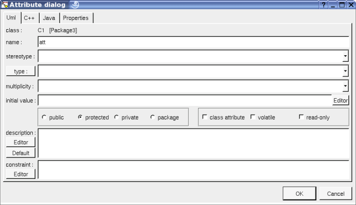
The first tab concern the UML characteristics, by default an attribute is an instance member (not a class member), is not volatile and is not read-only. Each other tab is link to a specific language : with BOUML you may design in several languages at the same time. For instance the HTML generator implementation is done in C++ and Java both.
Set the type to int, choosing among the predefined types list (modifiable through the generation settings) or typing int.
Go in the C++ tab (clicking on C++) :
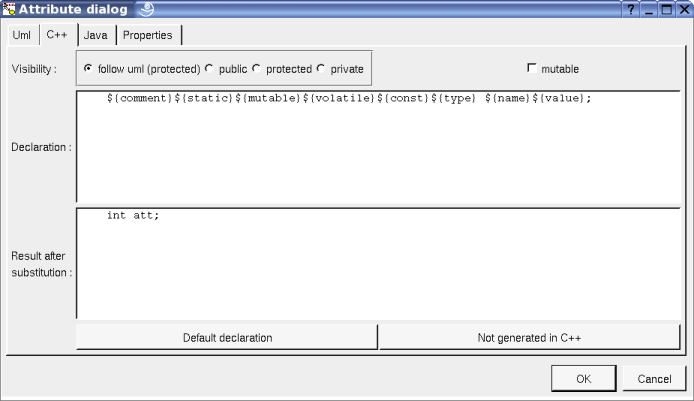
As you can see, the visibility for C++ is the UML one by default, but this is not mandatory to allow to help to not have the same visibility for instance in C++ and Java, and in C++ an attribute may be mutable.
The text behind declaration is editable, not the one behind result after substitution which shows the source code as it will be generated by the C++ generator (supposing you don't modify it !). Except for the keywords signaled by ${} and the user properties signaled by @{} all the other characters are generated unchanged, including the new line. It is not difficult to understand that ${type} is replaced by int and ${name} by att, both set in the UML tab. This also means that if you replace ${type} by aze the generated type for att in C++ will be aze, etc ...
Perhaps you have coding rules and for instance in C++ the name of an attribute must start by '_' ? Of course you may rename the attribute _att, but to see the '_' in the class diagram is not very pretty, it is better to add the '_' before ${name} :

Go in the Java tab :

The principle is the same, applied on Java.
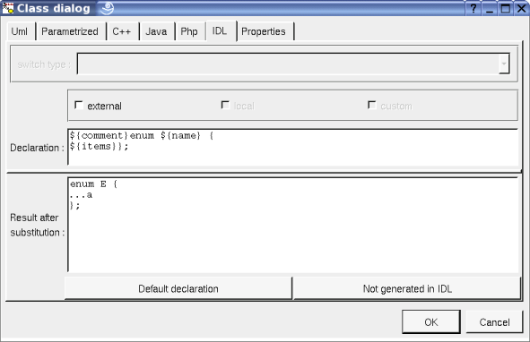
It is not possible to see the Idl and Php definitions. Why ? Remember, at the beginning I ask you set the toggle for C++ and Java in the Languages menu, so the definitions for the non toggled languages are hidden. Close the dialog hitting on ok, ask for all the languages through the menu Languages, reedit the attribute and go in the IDL tab :

The declaration is empty ! This is also because Idl was not set in the menu Languages. Hitting the button Default State declaration we have :

First the visibility is private rather than protected because protected doesn't exist.
Furthermore ${type} is replaced by long rather than int, this is because the type int doesn't exist in IDL, and the better target is long, magic !
They are other type conversions automatically done by BOULM, for instance if you choose any in UML you will have void * in C++, Object in Java and any in IDL. Obviously these conversions are not hard coded, they are set through the generation settings.
Go in the Php tab and ask for the default declaration :

This is a definition for Php5, if you want to use Php4 the better is to change the visibility to package, and the definition will be :

The definitions given the default forms with the keywords may also be modified through the generation settings, this allows you to add the '_' to name the attribute in C++ as above etc ... look at the reference manual for more. Remark : when you change the generation settings, the definition of the already existing elements is not changed.
Hit ok to validate the changes.
Class drawing settings
In the class diagram only the name of the attribute and the operation are visible, not the types nor the visibility, call the class menu in the diagram and change three drawing settings like this :
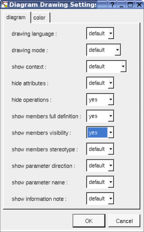
the class picture is now :

Do not hesitate to try the other drawing settings, and look at the reference manual for details.
Relations
We want to add a mono directional association from C1 to Administrator, hit the corresponding icon on the top of the diagram sub-window and add draw the relation as for the ones in the use case diagram :


As you can see the relation is added in the browser, by default its name is <unidirectional association>, edit the relation :

Like for the attributes we have the tab for UML and each language.
Because the relation is unidirectional only one role is editable. Like for the attributes and operation the default visibility is specified by the Class settings. The role name will produce the name of the member, and we found the flags already existing for the attributes : there no difference between a relation and an attribute for the generation point of view.
Name the relation admin and go in the C++ tab :

By default an association and an aggregation produce a pointer in C++, an aggregation by value will not produce a pointer. Obviously this default definition may be changed through the generation settings or just for this relation.
Go in the Java tab :

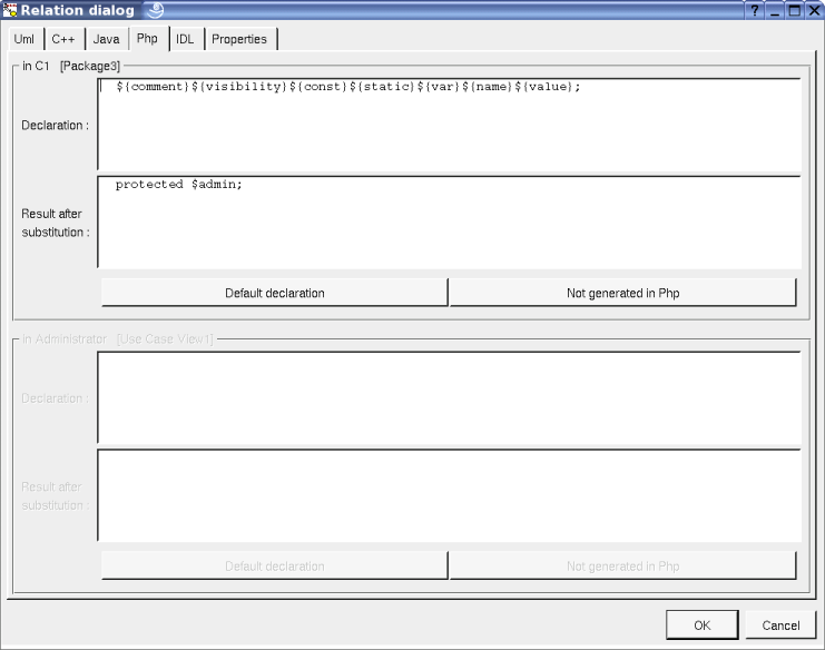
Go in the Php tab :
Go in the IDL tab :

Go back in the UML tab, change first the type of the relation to have an association (bi directional) then do the other modifications to have :

Go in the C++ tab and hit the button Default declaration for the two roles :

Go in the Java tab and hit the button Default declaration for the two roles :
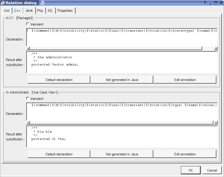
Go in the IDL tab and hit the button Default declaration for the two roles :

As you can see the default definitions depend on the type of the relation and the multiplicity, of course these defaults are modifiable through the generation settings.
The way a UML stereotype is projected for each language is also modifiable through the generation settings, as you can see above and below vector produces vector in C++ Vector in Java and sequence in IDL :

Press the button Ok and look at the diagram :

Because the relation is now bi-directional this one appears in the browser in C1 and Administrator (I mark them in the browser : they are red).
Define struct, union, typedef, enum
To define a C++ or IDL struct use the class stereotype struct, and edit the class using the Default declaration button on the desired language(s). In Java a struct is implemented through a standard class, of course the projection of a class stereotype from UML to a given language may be set through the generation settings, look at the dialog already shown below and read the reference manual.
To define a C++ or IDL union use the class stereotype union as for a struct.
To define for instance the C++ typedef T which is a pointer to a C1 : create the class T, and draw a dependency from T to C1

Edit the class and set the stereotype to typedef : the dialog is changed to indicate a base type, thanks to the dependency this one is set to C1, but you may change it . Go in the C++ tab :
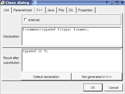
Of course the dependency in not mandatory, for instance to define typedef int turlututu
Add a '*' between ${type} and ${name} :

The enums are supported through the stereotypes enum and enum_pattern.
Create a class E , edit E to set its stereotype to enum and press Ok, call the menu on the class in the browser choose add item and name it a, then recall the menu and choose add attribute and name it b. Edit E and go in the C++ tab, ask for the default declaration :

As you can see, ${items} produce a (the '...' indicates that only the name is shown, not the full definition) but not b, this is because in C++ an enum only have items, attributes and operations are illegal.
Go in the Java tab, this is an enum for at least the JDK5
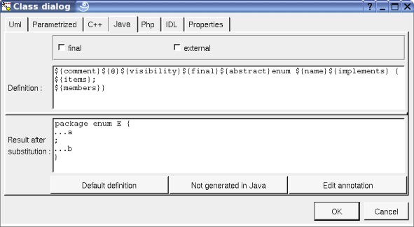
b is produced by ${member} because its stereotype is attribute allowing to separate the items and the attributes.
Go in the Php tab, b doesn't appears like in C++
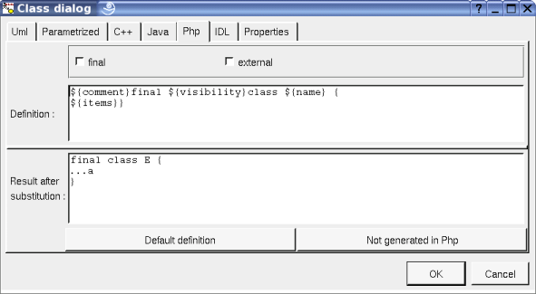
Go in the IDL tab, b doesn't appears like in C++
In the same way, if you add an operation in the enum this one will not be defined in C++, Php and IDL.
Now create the class OE, edit it to set its stereotype to enum_pattern and press Ok, look at the menu of OE : it is only possible to add items. There is no difference with the E in C++ and IDL, but in Java this is completely different because this kind of enum is supported by a class, this is for the Java release before the JDK 5:

An other time the form is defined through the generation settings.
I propose you to edit the item a in E and OE in all the language to see the definitions.
Code generation, deployment view, artifact
Perhaps you had seen the class menu entry Generate, try to generate the code for C1 : whatever the language you have the error “C1 : does not have associated artifact”. in UML 2 the artifacts represent the generated files, sources, object, library, executable, jar etc ..., and of course the code generation is done in a source, so you must specify which source. In the first releases of BOUML the code generation was associated to the components but because this is not compatible with UML 2 (UML 1 was very evasive on the subject) I had prefer to do the change, contrarily to many tools ...
An artifact may be placed only in a deployment view, create a deployment view in the package Package3 (this is not mandatory, you may place it in any package), let's suppose this name be Deployment view6
Now there are two ways to associate to each class an artifact of kind source and named like the class. The long way is to do for each class : create an artifact in Deployment view6, edit it to name it like the class, to set its stereotype to source and to associate it the class. The second way is better to associate several classes : associate Deployment view6 to Class view4 (because it contains C1 etc ...) editing Class view4 :

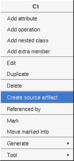
Thanks to this association when you call the menu of C1 and the other classes in Class view4 in the browser you may choose create source artifact and the appropriate artifact is created, do that for C1 :

Edit the artifact (you may select it calling the menu of C1 and choosing select associated artifact) and go in the tab associated classes :

C1 is associated to the artifact and you may associate several classes, in this case several classes will be produced in the same source file, you can change their order selecting an associated class and using go up/down.
Three tabs are not availables :
Php source because the associate classes (here C1) doesn't have a definition in Php,
Idl source because the associate classes (here C1) doesn't have a definition in IDL,
Associated artifact because the stereotype of the artifact is source. If the stereotype is not source you may associate artifacts to an artifact for instance to indicate which artifacts compose an executable (this way is used by the plug-out genpro).
Look at the other tabs and refer to the reference manual for details
Create an associated artifact for T, O and OE.
Try to generate code, this is possible calling the menu on each class, or on their class view, or the package containing the view etc ... up to the project level, in this case you may also call for the generation in the menu Tools. If you do that you have an other error because BOUML doesn't know where the files must be generated, the artifacts gives their names not their path !
It is possible to specify an own directory in each package (you may also specify a namespace / package / module), it is also possible to specify a directory (or a base directory) for all the project in the generation settings. Call the menu of the project in the browser (right mouse click on foo) and choose generation settings, go in the last tab named Directory and specify a directory for C++ and Java, for instance /tmp for both (choose another and better directories in the future !), validate (button Ok).
Now if you ask for the code generation you will have something generated. Ask for the generation a second time for the same language : the trace indicates that the files are not modified, because this is useless. Note that the code generators really check that the files already have the right contain, in case you change a file through an external editor and re-ask for the generation the modified file will be rewritten. This means that even this is not the faster way, you may ask for the code generation on the project and the date of the already generated files will not change, for the pleasure of your Makefiles or equivalent.
Epilogue
Now you are ready to start to use BOUML ... and to read the reference manual because this tutorial only contain a little part of the features of BOUML.
To finish don't forget that :
BOUML may be extended writing plug-outs. A plug-out may be developed in C++ or Java, look at the existing plug-outs as example.
When you don't know how to do to have a desired generated code, the better is probably to write (a part of) this code by hand in file(s), and to do a reverse in a new and empty project (to not pollute he current one) and to look at the result. Obviously the reverse may also be used to constitute a project.
Java programmers : use the plug-out Java Catalog !
Happy modeling !
Bruno Pagès